
HOME HEATING · INDEPENDENT ADVICE
Air Source Heat Pumps
How air source heat pumps work, what is inside the outdoor unit, and the practical decisions that matter before installation.
HOW A HEAT PUMP WORKS
Four stages. One continuous cycle.
01
Collect
A fan draws outdoor air across the evaporator.
02
Compress
The compressor raises the refrigerant pressure and temperature.
03
Transfer
Heat passes through a condenser into the heating circuit.
04
Expand
An expansion valve lowers refrigerant pressure for the next cycle.
THE PRINCIPLE
Heat from the air, even on cold days.
An air source heat pump (ASHP) transfers existing thermal energy from outside air into your home. Electricity runs the compressor, fans and pumps; it does not have to supply every unit of heat delivered. That is why a correctly designed heat pump can deliver several units of heat for each unit of electricity consumed.
A heat pump can be a significant investment. The outdoor unit is only one part of the system: radiators, pipework, controls, hot-water storage and the property’s heat loss all influence the finished design.
THE MAIN COMPONENTS
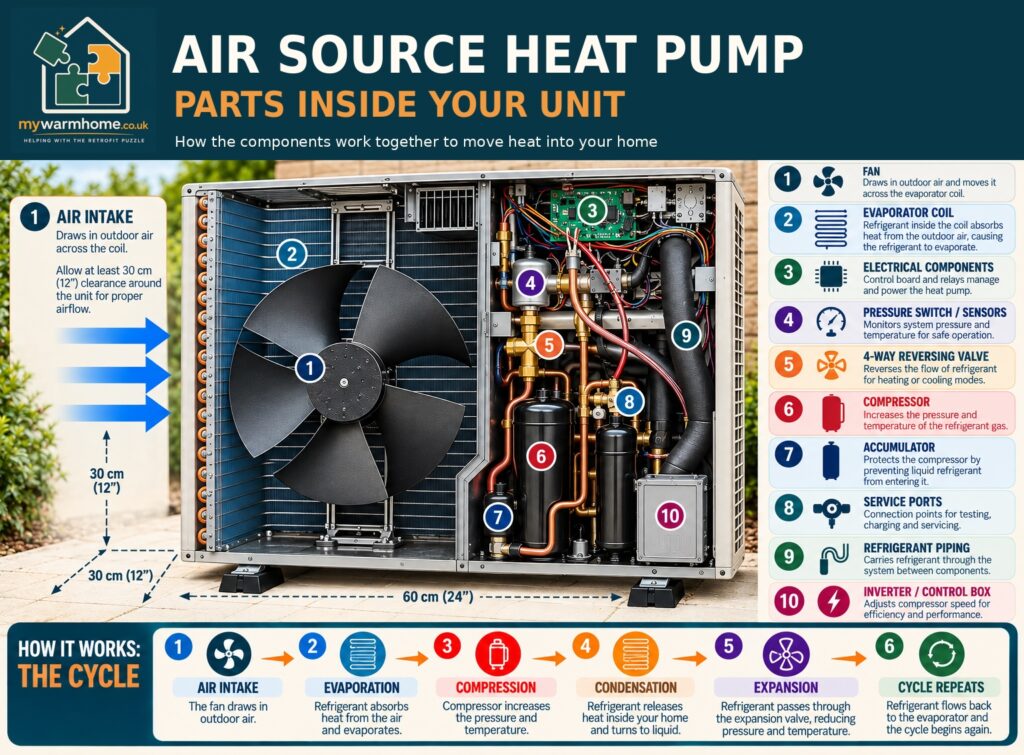
Fan and evaporator
The fan moves outside air across an evaporator coil. Refrigerant circulating inside the coil absorbs heat and boils at a low temperature and pressure.
Compressor
The compressor draws in refrigerant vapour and increases its pressure and temperature. This makes the refrigerant hot enough to pass heat into the home.
Condenser
In the condenser, hot refrigerant releases heat to the heating-water circuit and condenses back towards a liquid. The refrigerant does not normally mix with the water supplied to radiators.
Expansion valve
The expansion device lowers the refrigerant pressure. Its temperature then drops so it can collect more energy at the evaporator.
Sensors and controls
Temperature sensors, pressure controls, fan-speed control, circulation pumps and defrost management work together to balance output, efficiency and safety.
Common refrigerants include R32 and R290 (propane). Their safety requirements and environmental impacts differ. Equipment selection, siting and handling must follow the relevant manufacturer instructions and applicable regulations.
TWO MAIN ARRANGEMENTS
Monobloc or split?
Both arrangements use the same refrigeration principle. The key difference is where the sealed refrigerant circuit and heating-water interface are located.
Monobloc
The refrigerant circuit is factory assembled in the outdoor unit. Insulated water pipework connects the heat pump to the indoor heating system. External pipework requires appropriate frost protection.
Split system
Refrigerant pipework connects an outdoor unit to an indoor unit, often called a hydrobox. Refrigerant installation and commissioning require appropriately qualified engineers.
SYSTEM DESIGN

In most monobloc designs the fan, evaporator, compressor, condenser and expansion device are housed outdoors. Warm water travels between the unit and the internal heating system.
Advantages
- Factory-assembled refrigerant circuit.
- No field-installed refrigerant lines between outdoor and indoor units.
- Often straightforward hydraulic connections.
Points to check
- External water pipes need robust insulation and suitable frost protection.
- Pipe routes and pump duties must be designed for required flow rates.
- Outdoor siting must allow access, ventilation and drainage.
SYSTEM DESIGN
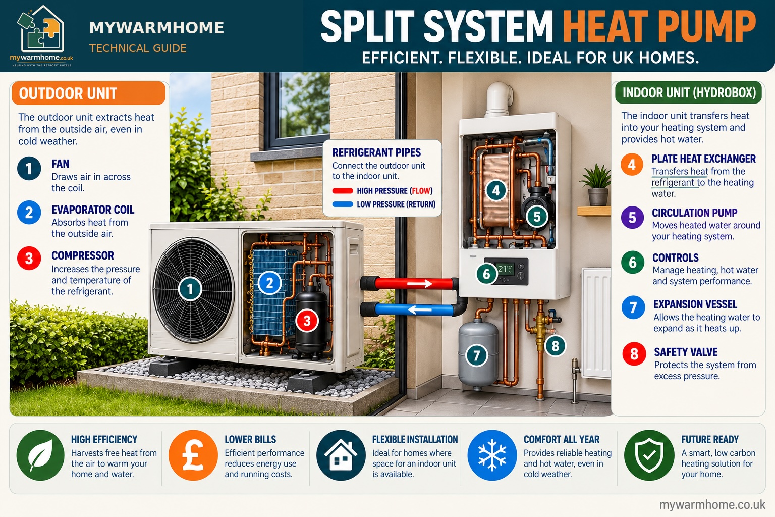
In a typical air-to-water split system, the outdoor unit contains the fan and evaporator while refrigerant flows to an indoor heat exchanger or hydrobox. The exact component arrangement varies by manufacturer.
Advantages
- No external heating-water connection between the two units in a conventional refrigerant split system.
- Can offer more flexibility in plant-room and pipework layout.
- Can reduce external water freezing exposure.
Points to check
- Refrigerant pipework requires qualified installation, testing and commissioning.
- Manufacturer limits apply to line length, height difference and refrigerant charge.
- Indoor space and service access are needed for the hydrobox.
INDOOR EQUIPMENT
What does a hydrobox do?
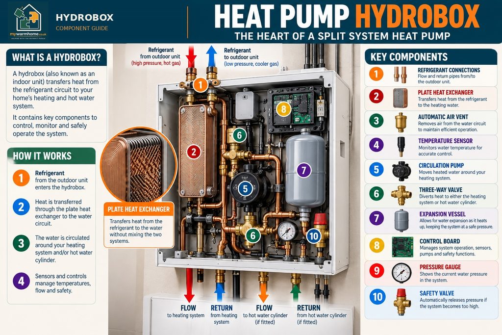
A hydrobox is an indoor unit that connects the refrigeration and water sides on many split systems. Depending on the model, it can contain a plate heat exchanger, circulating pump, electrical controls, safety devices and other hydraulic components.
Some systems combine the hydrobox with a hot-water cylinder. The layout should be based on the manufacturer’s design rather than assuming every installation needs a separate buffer vessel.
SYSTEM DESIGN
BEFORE THE INSTALLATION
Good design starts with the house.
Room-by-room heat loss
A proper heat loss assessment identifies how much heating each room needs at the design outdoor temperature.
Radiator and pipework sizing
Radiators must be checked at the proposed flow and return temperatures. Existing pipework must support the required flow without excessive resistance or noise.
Insulation and ventilation
Improving the building fabric can reduce heat demand. Ventilation should remain appropriate for the property and occupancy.
Weather compensation
Controls can vary the heating flow temperature with outdoor conditions. Correct commissioning of the heating curve can improve comfort and efficiency.
SITING AND PRACTICAL DETAILS
Where should the outdoor unit go?
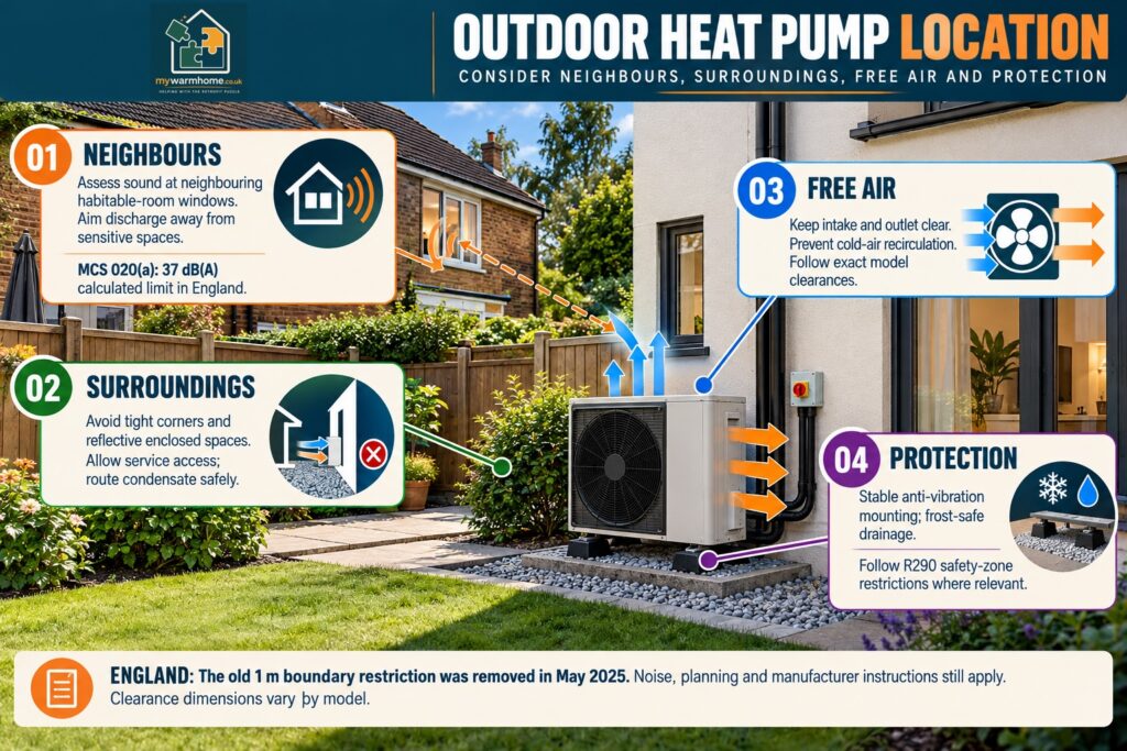
- Provide unobstructed airflow and manufacturer-specified servicing clearances.
- Consider neighbouring properties, bedrooms and other noise-sensitive areas; applicable planning and noise requirements must be checked.
- Arrange defrost-water drainage to avoid pooling and icy paths.
- Protect exposed water pipework from heat loss, weather and freezing in accordance with the system design.
- Check electrical supply, protection, isolators and any network notification or application requirements.
- Plan for access during inspection, cleaning and servicing.
Do not box in an outdoor unit unless the enclosure is specifically designed and approved to maintain airflow and service access.
SYSTEM DESIGN
REALISTIC EXPECTATIONS
Running costs and solar PV.
Ask installers for an estimate of annual heat demand, expected seasonal performance, electricity consumption and the assumptions behind running-cost estimates. COP is a performance measure under particular conditions; seasonal performance is more helpful when considering annual energy use.
Solar PV can offset some heat pump electricity use, but winter heating demand often coincides with reduced solar generation. The two systems can complement each other without being perfectly matched.
QUALITY & HANDOVER
What paperwork should you receive?
- A documented heat-loss assessment and system design.
- Details of the installed equipment, emitter and pipework requirements and control settings.
- Electrical certification appropriate to the work undertaken; new circuits and minor alterations are documented differently.
- Commissioning and handover records, operating instructions and warranty information.
- Relevant certification and scheme paperwork where applicable.
- Information on hot-water hygiene controls, maintenance and servicing.
UK requirements vary by jurisdiction and scheme. Check the current Building Regulations, relevant MCS standards, manufacturer instructions and funding conditions for the specific installation.
FURTHER RESEARCH
Heat pump manufacturers.
Examples of manufacturers and suppliers represented in the UK market. This is a reference list, not a recommendation or assessment of product suitability.
UK and European
INDEPENDENT GUIDANCE
A useful starting point.
The best heat pump is not necessarily the largest or the most expensive. It is the one correctly sized, designed and commissioned for the property and the way its occupants use it.
For more detail, read the heat pump technical guide, visit MCS, or review the HSE guidance on Legionella.