Category: Heating Controls

  • Complications of controls

    For someone used to a simple dial thermostat, navigating icons, settings, and scheduling interfaces can feel unnecessarily complex.

    Controls for modern heating systems are often designed with flexibility in mind—but that flexibility can come at the cost of usability, particularly for older homeowners. Many systems now rely on layered menus, small touchscreens, or app-based controls that assume a level of digital confidence that not everyone has. For someone used to a simple dial thermostat, navigating icons, settings, and scheduling interfaces can feel unnecessarily complex. Even basic adjustments like increasing the temperature can become frustrating if they’re buried behind multiple steps.

    There’s also a strong reliance on smartphones and apps, which doesn’t always reflect reality. A significant number of older people either don’t use smartphones at all or use them in a very limited way. Small screen sizes, poor contrast, and fiddly controls can make apps difficult to read and operate—especially for those with reduced eyesight or dexterity. On top of that, concepts like Wi-Fi connectivity, accounts, and software updates can create barriers that simply don’t exist with traditional controls. When heating becomes dependent on an app, it can leave some users feeling locked out of their own system.

    Technology awareness plays a big role too. Many modern interfaces assume familiarity with common digital behaviours, swiping, tapping icons, navigating menus, but these aren’t universal skills.
    For older users, there can be a lack of confidence in “trying things,” especially when there’s a fear of pressing the wrong button and causing a problem. This often leads to systems being left on default settings, or worse, used incorrectly, impacting both comfort and efficiency.

    So what’s available? Encouragingly, there are still more accessible options. Some manufacturers offer simplified thermostats with large buttons, clear displays, and minimal menus, focusing only on core functions like temperature up/down and on/off.
    Others provide wired controls that stay in a fixed location, avoiding the need for apps altogether. There are also programmable thermostats with physical buttons and high-contrast screens, designed specifically with readability in mind. In more advanced systems, it’s sometimes possible to pair a smart setup with a basic user interface for day-to-day use, leaving the more complex controls to installers or family members if needed.

    Ultimately, good design should work for the person using it, not the other way around. When specifying heating controls, it’s just as important to consider usability as it is efficiency. A system that’s easy to understand and operate will always perform better in real life than one packed with features that never get used.

  • Its More Than A Balancing Act.

    Its More Than A Balancing Act.

    Balancing a central heating system properly is what separates a working” system from an efficient, comfortable, and compliant one

    1. Pre-checks are critical.

    Before touching lockshield valves:

    • System fully bled (no air)
    • Correct system pressure.
    • Pump operational and correctly set.
    • All TRVs fully open.
    • Room thermostat calling for heat.
    • Boiler at normal operating temperature (flow ~70°C typical).

    2. Identify radiator order

    You need to know flow sequence:

    • First radiators = closest to boiler
    • Last radiators = furthest away

    3. Fully open all lockshield valves

    • Remove caps (if still on!).
    • Open all lockshields fully (anti-clockwise).

    4. Measuring temperatures.

    Measuring temperatures when balancing radiators can feel a bit daunting at first, but a digital thermometer is inexpensive and easy to use. Most are simple point-and-click devices, allowing you to quickly take readings from the flow and return pipes.

    For greater accuracy, clamp thermometers can be used, although they tend to be more expensive.

    The flow and return pipes can be installed either way, but typically the TRV is fitted on the flow side. If you’re unsure, it’s worth checking while the system is heating up one side will warm up faster, helping you identify the flow

    • Flow temperature (T₁) (going into radiator)
    • Return temperature (T₂) (going from radiator)

    A temperature drop (ΔT) of about 11°C (older systems ~11–12°C, modern condensing often 15–20°C depending on design)

    5. Start balancing (closest radiator first)

    For each radiator:

    1. Let system stabilise.
    2. Measure ΔT.
    3. Adjust lockshield valve only.

    If ΔT is too small (e.g. 3–5°C):

    Too much flow,
    Close lockshield slightly,

    If ΔT is too large (e.g. 20°C+):

    Not enough flow.
    Open lockshield slightly.

    6. Work progressively through the system

    • Move from radiator to radiator.
    • Always allow 2–5 minutes stabilisation after each adjustment.
    • Recheck earlier radiators as adjustments affect the system.

    7. Final system check

    Once all radiators are balanced:

    • All rooms should heat evenly
    • Boiler should run more steadily (less cycling)
    • Return temperatures should be lower → improves condensing efficiency

    Professional targets (important)

    • Typical ΔT:
      • ~11°C (traditional UK benchmark).
      • 15–20°C for modern condensing optimisation.
    • Even heat distribution across property.
    • No “first radiator scorching / last radiator cold” issue.

    Common mistakes.

    • Balancing with TRVs partially closed.
    • Not measuring temperatures (guesswork).
    • Adjusting both valves instead of lockshield only.
    • Rushing without stabilisation time.
    • Ignoring pump speed or system design.

    Pro tips

    • Use clamp thermometers instead of infrared guns (more accurate).
    • Slightly underfeed first radiators to prioritise system distribution.
    • Aim for lower return temps to maximise condensing boiler efficiency.
    • Consider weather compensation or smart controls after balancing.

    A poorly balanced system:

    • Reduces heat pump performance massively.
    • Causes overheating/underheating problems.
    • Fails to meet expected SAP or EPC improvement.

    A properly balanced system:

    Maximises efficiency.
    Improves comfort.
    Supports compliance.

  • PAS!

    PAS!

    A Publicly Available Specification (PAS) is a document that defines good practice standards for a product, service, or process. 

    PAS 2030/2019 here. information on Pas 2035/2023 here.

    A Publicly Available Specification (PAS) is a document that defines good practice standards for a product, service, or process. 

    PAS 2035/2030 are linked frameworks that outline best practices for retrofitting homes in the UK to enhance energy efficiency. 
    While PAS 2030 focuses on the quality of the installation processes, PAS 2035 ensures that the retrofit is appropriate for the building as a whole.
    Current PAS documents can be downloaded here.

    It’s a crucial component of the UK government’s strategy to boost building efficiency and reduce carbon emissions. Adopting a “whole house” approach, PAS 2035 considers the home’s environment, occupancy, and the homeowner’s objectives, ensuring that retrofit projects address key aspects such as insulation, ventilation, occupancy, and building fabric to support long-term sustainability.

    Although not a regulation, PAS 2035 is a publicly available specification (PAS), developed to address shortcomings of previous schemes following the Each Home Counts Review.

    PAS 2035 compliance is mandatory for all publicly funded projects, including those supported by the Energy Company Obligation (ECO), and Warm Home Fund. We also have a route called licence plus which is run by Trustmark which does not need coordination as part of its process!. This is mainly aimed at self funding retrofit but using installers that are roughly following the current PAS process. Whichever mechanism is to be used, the property occupier should request details of which route the process follows pre-install.

    PAS 2035 has its strengths, but also notable limitations. If everyone in the supply chain, assessors, coordinators, designers, and installers adheres strictly to the process, the framework should work effectively.
    However, lapses in monitoring and inspection can lead to issues. Unfortunately, “technical monitoring” for most UK schemes is minimal, and no longer performed by Ofgem, meaning that failings can go unnoticed, leaving property occupiers unaware of potential problems. Hopefully this will change with future consultations. 

    The retrofit process involves a range of participants, including canvassers, lead generators, social marketeers, assessors, designers, coordinators, installers, and a limited number of technical monitoring agents. This complexity, along with regulations, updates to rules and red tape, can create confusion and drive up costs.

    The standard will transition from PAS 2035:2019 to PAS 2035:2023 in March 2025.

    Protecting the Property Occupier!

    PAS 2035 outlines several requirements for both pre and post installation stages. One of its most valuable aspects is the involvement of a retrofit coordinator throughout the process.

    The coordinator’s primary role is to safeguard the interests of the property and its occupants, ensuring the retrofit is carried out effectively and sustainably.
    In an ideal scenario, the retrofit coordinator would operate independently, free from any conflicts of interest and most importantly in my opinion has performed in the retrofit assessment area. However, this level of impartiality is often difficult to achieve in practice. 

    By understanding the processes outlined below, you’ll hopefully gain the knowledge needed to ask informed questions and engage with some confidence at various stages of your retrofit journey.

    In practice.

    If the property / occupants have met the requirements of a funded scheme, then the installation or funding company will arrange for a retrofit coordinator to instruct a visit from a retrofit assessor. The coordinator is the first in the process as this is the stage that the property classification is usually identified (traditional, non-traditional etc.)

    The assessor should try to get a picture of what the typical energy use entails and also what is expected by improving the property. Lots of photographs will be taken as an EPR (energy performance report) will be produced at the end.
    This is basically a reference EPC (energy performance certificate) but does not get published on the central register. (when EEM work is completed, a new EPC should be produced, ideally the original assessor as they will have the original data)

    Some quick guidance on what the assessment entails and why!

    • First things are age and condition. This is to allow a retrofit coordinator to classify the property and create a plan that allows a fabric first approach that works with the natural balance of the property and highlights all potential issues.
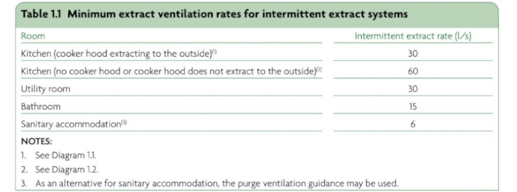
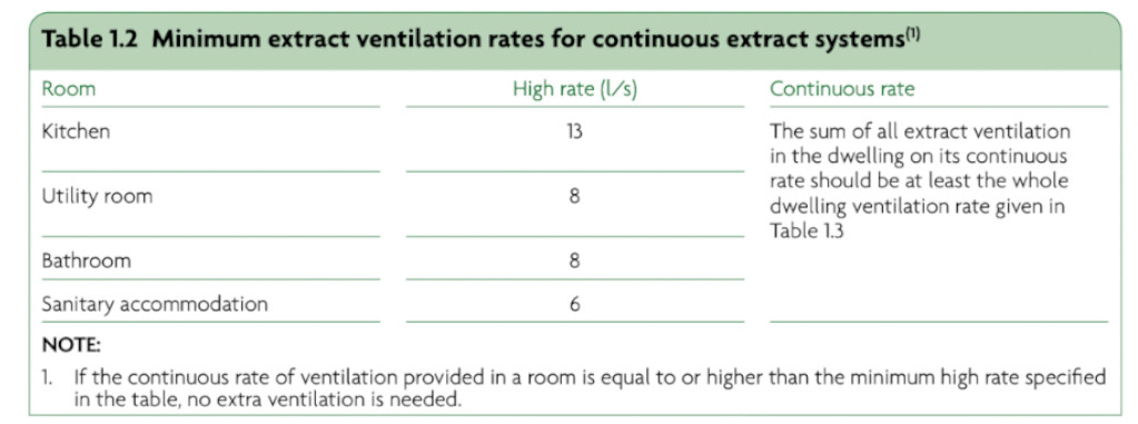
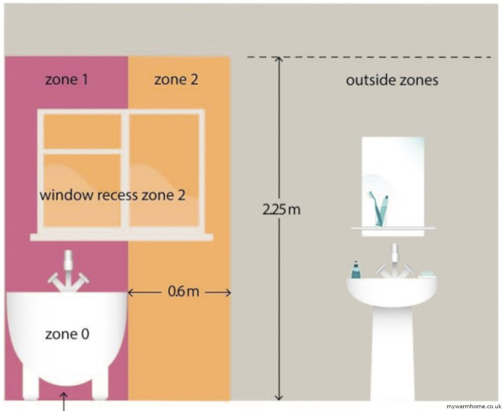
    • Existing Ventilation in wet rooms photographed and noted.
      This is because all insulation packages require moisture to be controlled post installation. Some insulation situations require upgrades due to the design and current regulations.
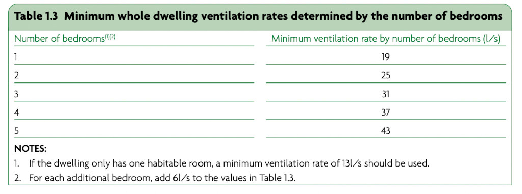
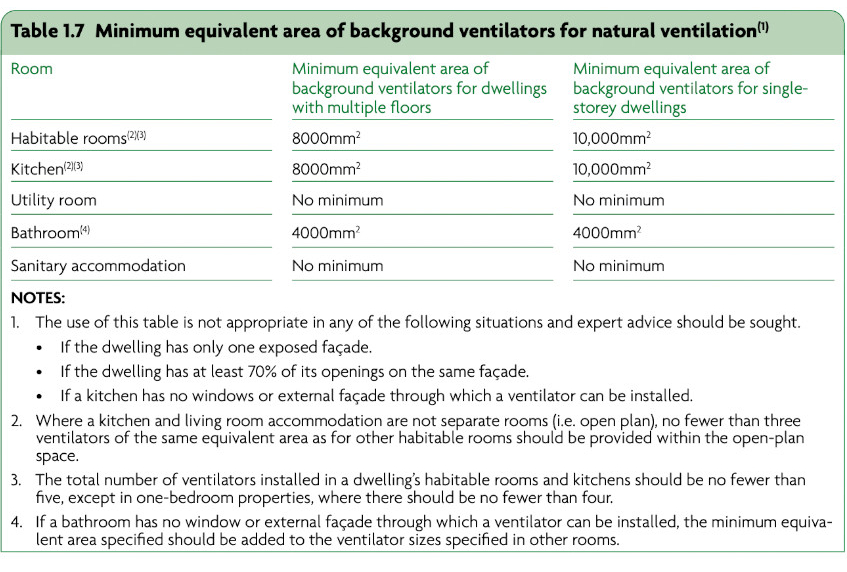
    • Existing background ventilation photographed and noted.
      This is because all insulation packages require the replenishment of air post installation. Some insulation situations require upgrades due to the design and current regulations. Installers may use a pulse or blower test may be performed to validate if upgrades to background ventilation are necessary.
    • Fuel burning appliances noted.
      This is especially relevant with open flued appliances like gas, wood/coal burning fires etc. Ventilation requirements for combustion may need to be installed or verified adequate, especially after extraction units have been added or improved.
    • Whole footprint of property measured, including all windows/glazed doors.
      This allows to distinguish what is a “heat loss area” in more detail, and also potential solar gains.
    • Plenty of images of outside. This is to show the condition of building elements, including damp course and drainage services (gutters, downpipes, soil pipes).

    Access to all rooms are required as is the loft space, basements and visual inspections of all external walls and areas. All ventilation present will be recorded and door undercut measurements should be taken.
    The assessment can take longer if more than one installation is being carried out, i.e. wall insulation, loft, and heating.

    A report is then generated to give a rating of the properties’ energy performance from “A (very good) to a (G) very poor”. Information is then made available to the retrofit coordinator.
    All data is uploaded to the *Trustmark data warehouse, which forms a property plan and can be accessed by involved parties.

    The coordinator will then look at all the data to see if improvements need any special design attention and intervention due to condition, age of property and location. If all looks OK then a ventilation strategy will be put in place depending on installation requirements.
    Some other documents are required, like a medium term improvement plan, which will create future scenario’s for improvements. 

    A retrofit designer will need to be consulted to design the proposed installation measure(s) if deemed necessary.
    We can take designers of certain measures as being members of a trade body. For example, a Gas Safe engineer installing a gas boiler, a SWIP trained installer performing IWI to a traditional non-heritage building, MCS accredited installer for solar and heat pumps. 

    A professional member of a Chartered Institute will be required, especially on buildings with heritage values or interacting insulation systems (wall and floor insulation being installed together, for example).
    It is up to the retrofit coordinator to validate that the designers and installers are all suitably qualified.

    * The TrustMark Data Warehouse was created to address several recommendations in the  Each Home Counts review  commissioned by the Government in 2015.

    The retrofit plan is executed.

    This is what the installers are expected to perform to meet the current PAS. Each measure (installation or improvement) will have its own route and requirements, and brief information be found on each section within this site.
    The plan will provide steps for the current and potentially future improvements. A fabric first approach should always be used, this means insulation before any heating works need to be carried out. Soft touches should also be part of the fabric first approach like heating controls, draught proofing and low energy lighting.

    The occupants should be informed of all work. It should be the co-ordinator and installers who contact the occupiers to inform them of the process that the retrofit project will follow. Dates, times, and conditions required will need to be discussed and agreed upon. 
    This may include removal of furniture to prevent damage or the arrangement of alternative living arrangements throughout the works (especially on internal wall insulation). It may include preinstall remedial works to the property structure or minor repairs like broken windows, failing of rainwater removal (poor guttering) and wall pointing.

    Get all this information in writing or in an email to reference at a later date if required. 
    Make notes of Installers contact details, coordinators, and assessors names and numbers. This can be invaluable if you need to contact anyone involved in the process.
    You can do research on installers, co-ordinators, assessors and designers here as they all need to be Trustmark registered.

    The Installation.

    Once agreed and a plan has been discussed, the installation will begin. If an insulation measure is being installed, then validation is required that either the current ventilation is sufficient or insufficient. The assessment would have highlighted any shortfalls, and the installers may ask to perform an air tightness test. This can be carried out using a pulse test, this may be performed to allow installers a way of emitting undercuts and background ventilation from the installation, but controlled ventilation is always a good way to manage moisture. 
    The ventilation should always be installed or upgraded first, or at least core vents and wiring set in place if wall insulation being installed.

    The *retrofit coordinator should make a site visit if the measure is deemed high risk which includes IWI, EWI, UFI, FRI, PHI and RIR. (*this will be a mandatory requirement from early 2025)
    The next stage will be the installation phase of the main improvements. 

    The Handover.

    Depending on the complexity of the installation, the duration can range from a single day to several weeks. This timeline should have been discussed and documented during the early planning stages.
    Before signing off on the work completed by the installation company, ensure you are fully satisfied that all agreed tasks have been completed to your expectations. Additionally, verify that any damages have been repaired or compensated. Make sure you have received all necessary handover documents, including warranties, guarantees, compliance certificates, insurance policies, gas certificates, and electrical certificates. Some certificates and warranties may come via post or email after the installation, if this is the case then ask for written clarification that they will be provided. All these documents are part of the works and may be needed if selling the property or for insurance purposes.

    Insurance Backed.

    To be PAS 2030 certified, installers must have an Insurance Backed Guarantee provider to ensure their customers are protected. They must also have adequate insurance coverage, including liability insurance, to protect homeowners.

    What is an insurance backed guarantee? Installers will provide their own written workmanship guarantee (this is very important to get a copy of in case of any poor installations). This will outline a guarantee period, during which the installer will return and fix any faults resulting from faulty workmanship.
    The insurance backed guarantee only comes into effect if the original installation company ceases trading through lets say bankruptcy!. Ask for details of the company providing the guarantee, and then do your research. 

    All Insulation installed under PAS.

    Each insulation installation will follow the same route as regards with ventilation on PAS. This should be explained by the retrofit coordinator and the installers. The basics are that background ventilation (usually trickle vents) will be provided unless an air permeability test is performed and validates the need to omit from the installation.
    Wet room ventilation is always required, but can vary with different insulation situations. (see below)
    If PIV (positive input ventilation) is being installed, then request details of why this choice is being taken, installers or retrofit coordinator will be able to guide you. (PIV will need maintenance, and it is placed in your loft space).

    Some insulation situations like the property not being 100% insulated (bathrooms and kitchens being omitted due to fixture removal difficulty) then the extract ventilation may need to be a dMEV system to mitigate risks of condensation.

    Pre-installation building inspection (PIBI)

    The Retrofit Installer should undertake a pre-installation inspection using a competent person, this means a person or persons who have relevant industry qualifications.
    The inspection shall be undertaken at a level of detail sufficient to confirm that the specified energy efficient measure can be safely and effectively installed at the designated location. Particular attention shall be given to potential moisture build up as a result of the installation and taking into account the fire safety of the dwelling and the functionality and/or safety of installed services (gas, electricity, water, telecommunications, etc.)

    Technical Monitoring.

    Technical monitoring is a form of auditing that highlights a set of given questions on compliance. This is not performed by the installation company, but they may have their own regime of quality control. The funders (energy companies) will use these reports to highlight and hopefully rectify failing. Sadly, this shows that even with all the rules and hierarchy within the process of PAS, failing still arise. More on technical monitoring here.

  • Regulations.

    Regulations.

    Building regulation’s basics.

    The Act for the Rebuilding of the City of London was passed in February 1667. It proposed that all new buildings had to be constructed of brick or stone against the future perils of fire. It also imposed a maximum number of storeys per house for a fixed number of abodes to eliminate overcrowding. This was probably the first set of England’s building regulations, the devolved nations have their own regulations. 

    If work is being carried out on UK funded schemes (like warmhomes), then the current PAS works alongside the current building regulations. This sets out how the processes and standards will hopefully prevent failure to the homeowner/tenant.
    Below are the approved documents for England.

    In most cases the regulations are the same for each part of the UK, but variations may exist, and you should reference the specific nation for current standards.

    Extract Ventilation excerpts, Part F. 

    Information and images below from Part F.
    Extract ventilation to the outside should be provided in all the following spaces.

    • Kitchens.
    • Utility rooms.
    • Bathrooms.

    Sanitary accommodation.
    Extract ventilation can be intermittent or continuous.
    Minimum extract ventilation rates are in litres per second (l/s) for intermittent operation.
    Minimum extract ventilation rates for intermittent systems are given in below table 1.1.
    Minimum extract ventilation rates for continuous operation extract systems are given in below table 1.2.
    Minimum extract ventilation rates for the whole dwelling are given in below table 1.3.
    Extract ventilation terminals and fans, not including cooker extract hoods, should be installed to comply with both of the following conditions.

    • As high as is practicable in the room.
    • No more than 400mm below the ceiling.

    Where a cooker hood is used to extract to the outside, the height of the extract hood above the hob surface should be either as specified in the manufacturer’s instructions or, if no specification is available, between 650mm and 750mm (gas regulations also apply for gas hobs).
    Continuously running fans should be set up to operate without occupant intervention, but may have manual or automatic controls for selecting the high rate of operation. Any manual high rate controls should be provided locally to the spaces being served, e.g. bathrooms and kitchens. Automatic controls might include sensors for humidity, occupancy/usage and pollutant release. Controls based on humidity sensors may be installed in moisture-generating rooms (e.g. kitchen or bathroom) but should not be used for sanitary accommodation, where odour is the main pollutant.  Other types of automatic controls might be suitable. Where present, automatic controls should operate according to the need for ventilation in the space.

    Background Ventilation excerpts, Part F.

    Below information and images from Part F.

    Vents should be at least 1700mm (to reduce draughts) from floor level and should be controllable. The occupants should be able to reach ventilators.

    Ventilation should be controllable. Controls may be either manual (i.e. operated by the occupant) or automatic. Background ventilators should be at least 1700mm above floor level, to reduce cold draughts, but still be easy for the occupant to reach.
    Background ventilators with automatic controls should also have manual override.
    Where a combustion appliance is installed, any automatic controls must also ensure that the ventilation provided meets the requirements of Part J of the Building Regulations. If ventilators are installed on a funded scheme, then they should meet equivalent area to current PAS.

    U-Value Regulations at a glance.

    U-values for existing dwellings.

    • Roofs: 0.16 W/m²K
    • Walls: 0.30 W/m²K
    • Floors: 0.25 W/m²K

    U-values for windows and doors.

    • Doors with over 60% glazing: 1.2 W/m²K
    • Other doors: 1.0 W/m²K, with a limiting value of 1.6 W/m²K
    • Replacement windows: 1.4 W/m²K or a B for its window energy rating (WER)

    Bathroom Zones.

    For electrical installations in bathrooms certain electrical regulations exist. Zones are divided to allow appliances with electrical connections to be installed in each zone. link here.

    Boiler Flues.

    All boiler flues have to be installed with clearances set out by building regulations (Part J) and manufacturer instructions. 
    Some minimum basics are.

    • 300mm from an opening window
    • 300mm from ground level (boiler may be in basement)
    • 600mm from facing wall

    List of BS EN standards.

    BS EN 13162 to BS EN 13171: Thermal Insulation Products for Buildings.
    These standards specify the requirements for factory-made thermal insulation products used in buildings. They cover a range of materials, including mineral wool (BS EN 13162), expanded polystyrene (BS EN 13163), extruded polystyrene (BS EN 13164), and cellular glass (BS EN 13167). Each standard details the material properties, performance criteria, and testing methods to ensure the insulation meets the required specifications.

    BS EN 13162: Mineral Wool Products.
    This standard applies to mineral wool products, including glass wool and stone wool, used for thermal insulation. It covers the material’s properties, such as thermal resistance, dimensional stability, and water absorption, ensuring they meet rigorous performance and safety criteria.

    BS EN 13163: specifies requirements for expanded polystyrene (EPS) insulation products. It includes compressive strength, thermal conductivity, and moisture resistance parameters. This standard ensures that EPS products provide effective insulation and structural support.

    BS EN 13164: Extruded Polystyrene (XPS) Products
    This standard applies to extruded polystyrene (XPS) products, which are known for their high compressive strength and low water absorption. BS EN 13164 outlines the necessary thermal and mechanical properties, making XPS suitable for applications like perimeter insulation and inverted roofs.

    BS EN 13165: Rigid Polyurethane (PUR) and Polyisocyanurate (PIR) Foam Products.
    This standard applies to rigid polyurethane (PUR) and polyisocyanurate (PIR) foam products. It sets out requirements for thermal performance, dimensional stability, and fire resistance. Due to their excellent thermal properties, these materials are commonly used in wall, floor, and roof insulation.

    BS EN 13166: Phenolic Foam Products.
    This standard covers phenolic foam products, which are known for their high thermal performance and fire resistance. BS EN 13166 specifies the necessary properties to ensure that phenolic foam provides effective insulation in various applications.

    BS EN 13167: Cellular Glass Products.
    This standard applies to cellular glass products with exceptional moisture resistance and compressive strength. This standard ensures that cellular glass meets the required thermal and mechanical performance criteria for insulation applications.

    BS EN 13168: Wood Wool Products.
    Specifies requirements for wood wool products used for thermal insulation. It covers properties like thermal resistance, density, and moisture absorption, ensuring that wood wool provides effective insulation and acoustic performance.

    BS EN 13169: Expanded Perlite Products.
    This standard is for expanded perlite products, which are lightweight and have good thermal and acoustic insulation properties. Outlines the necessary performance characteristics for these products to ensure their effectiveness in building applications.

    BS EN 13170: Expanded Cork Products.
    This standard covers expanded cork products, which are known for their natural insulation properties and sustainability. It ensures that the expanded cork meets the required thermal and mechanical performance criteria for building use.

    BS EN 13171: Wood Fibre Products.
    Applies to wood fibre products used for thermal insulation. It sets out requirements for properties such as thermal conductivity, density, and moisture resistance, ensuring that wood fibre products provide effective and sustainable insulation.

    BS 476: Fire Tests on Building Materials and Structures.
    A series of standards that describe fire tests for building materials, including insulation. It assesses the fire resistance and reaction to fire of insulation products, ensuring they provide adequate protection and do not contribute to the spread of fire.

    BS EN ISO 6946: Building Components and Building Elements – Thermal Resistance and Thermal Transmittance.
    This standard specifies the calculation methods for determining the thermal resistance and thermal transmittance (U-value) of building elements, including walls, roofs, and insulation-covered floors. Accurate U-value calculations are essential for designing energy-efficient buildings and complying with building regulations.

    PAS 2035: Retrofitting Dwellings for Improved Energy Efficiency.

    PAS 2035 is a specification for retrofitting domestic buildings to improve energy efficiency. It covers the assessment, design, and installation of retrofit measures, including insulation. The standard aims to ensure a holistic approach to retrofitting, addressing potential issues such as ventilation, moisture control, and thermal bridging.

    Schemes and accreditation.