Technical monitoring involves technical inspections to ensure more the compliance than the quality of funded ECO installation projects. Some installation companies perform in-house checks during the installation process, which will usually be arranged directly with them.
Additionally, funders, such as energy companies, often employ independent technical agencies to perform monitoring who will be members of ATMA. These inspections are carried out on a small percentage of installations, so not every project will undergo this process. When selected, an independent technical monitoring agent will contact the property occupants to arrange a visit. While participation is voluntary, it is strongly recommended as through personal experience this is one of the few chances that failings can be picked up.
The purpose of technical monitoring is to assess the installation’s adherence to PAS standards, regulations and any health and safety concerns. However, there are limitations as inspectors cannot see behind walls, under solar panels etc! But if the retrofit process is carried out according to PAS, then evidence will be documented during installation, which will be shared and documented with the Retrofit Coordinator.
If any issues are identified, the findings are reported to the monitoring agency and then passed to the funders, who should address any deficiencies directly with the installer. It’s worth noting that technical monitoring rarely evaluates workmanship directly. Therefore, choosing reputable installers is crucial. Researching online reviews, social media feedback, and trade associations can help assess the quality you can expect.
What Technical monitoring agents look out for.
Boilers.
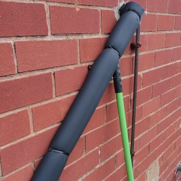
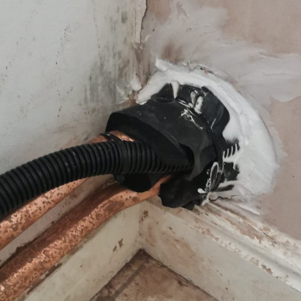
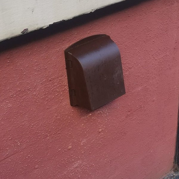
Condensate pipe run externally must be lagged with class 0 insulation, all gaps through walls that the installers have made should be sealed. Internal condensate pipes should meet current best practices.
The flue position and fall should be meeting manufacturers installation instructions and current regulations.
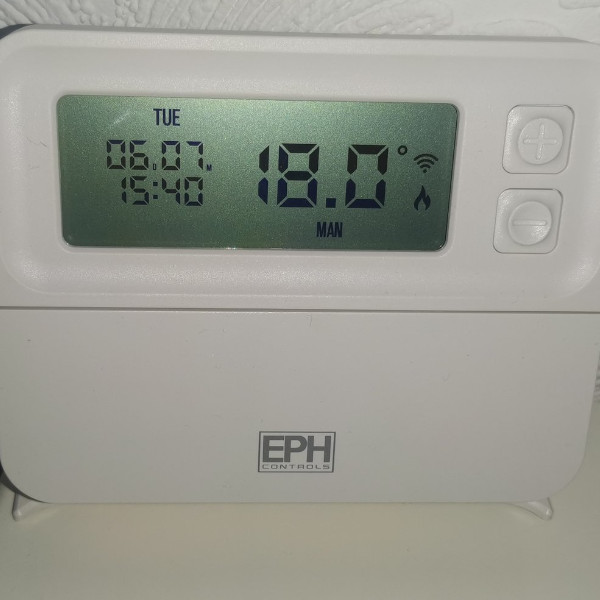
Room thermostats should be present and placed in a room without a radiator thermostat. (5.22 Part L) and be installed with boiler plus in mind.
Carbon monoxide alarm should be present and close to the installed boiler.
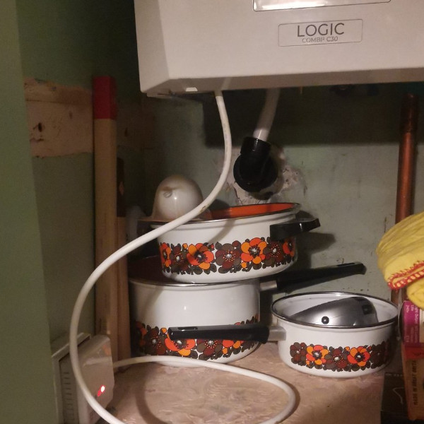
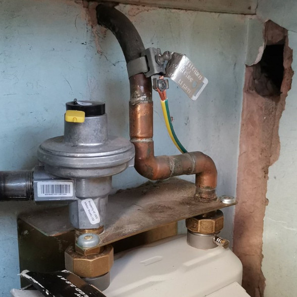
All electrical cables around the boiler need to be away from gas pipes, not clipped to pipes and adequately fixed.
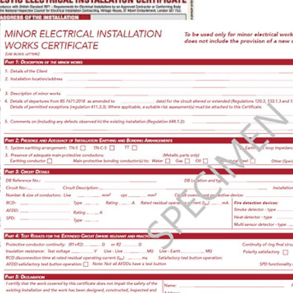
Minor works electrical certificate on site and completed.
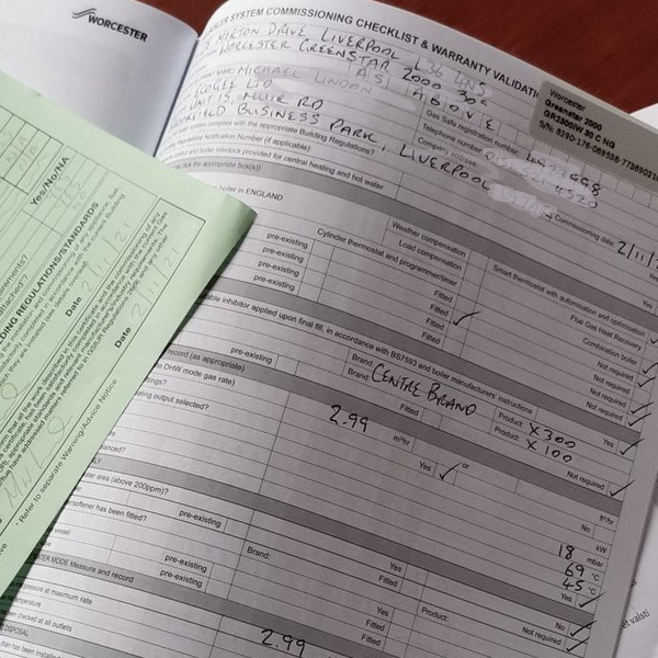
Boiler service manual with benchmark completed.
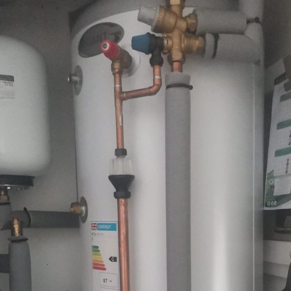
If new HW tanks have been added, then must be fully insulated and pipework around the tank insulated to prevent heat loss.
Class 0 Condensate Lagging
Poorly Installed Cables.
Room Thermostat
Electrical Certificate
Benchmark
Gas Bonding
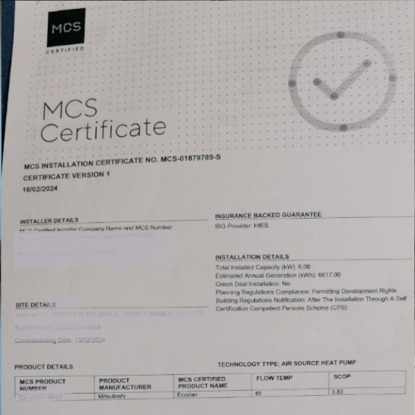
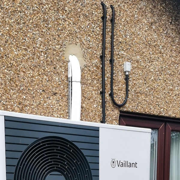
Air source heat pumps.
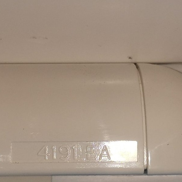
Condensate pipe must be lagged with class 0 insulation, all gaps through walls that the installers have made should be sealed and may also need to be sleeved.
The location of the heat pump should be at least 1 meter away from a neighbour’s property boundary. The noise level from the ASHP should not exceed 42 decibels (dB) at this distance. (check latest for details of changes. re distance and noises)
The location should be away from sleeping areas.
If new HW tanks have been added, then they must be fully insulated and pipework around the tank insulated to prevent heat loss.
Pressure relief valves from installed water tanks should have a visible tundish and if terminated outside should be caged.
Isolation valves should be fitted externally on the flow and return pipework.
All rooms should be heated.
Room thermostats should be present and placed in a room without a radiator thermostat. (5.22 Part L) This can be argued within the heat pump industry as the system is low temperature)
External weather compensators should be correctly positioned.
All installation and manufacturer documents should be on site or in electronic copy with the occupier.
Cage Protection
Tundish and Pipe Insutlation
Room Stat
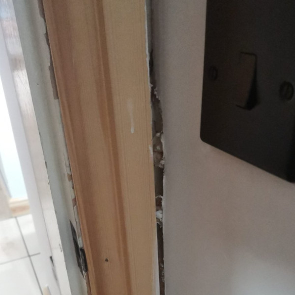
Sealed Internally
MCS
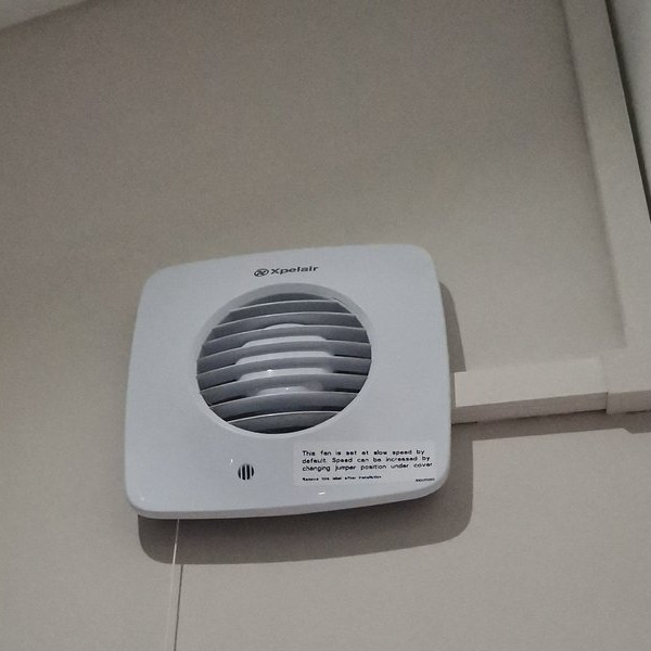
ASHP/ Sensor on Wall
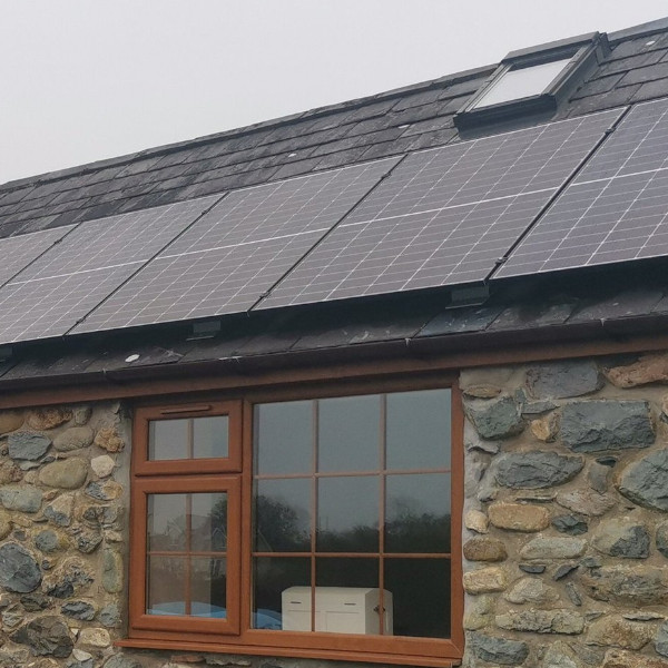
Solar PV.
Panels securely fixed to roof. (cannot always be visible).
Distance from edge of roof.
The inverter should be fixed to a fire retardant surface.
Watertight installation (no leaks from install)
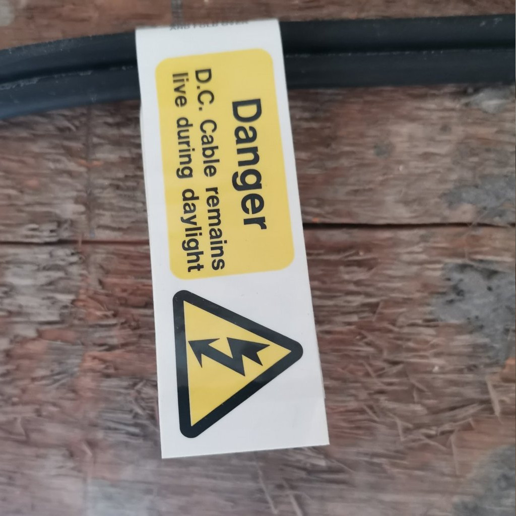
Cables from panels labelled as they run through each new areas (i.e. down the side of wall then into garage, each section should have DC labels)
Fire label near main consumer unit.
Isolation switches for AC and DC
All generation meters and switches labelled.
Schematic diagram showing array and switches.
Handover pack including MCS certificates, electrical installation and array information.
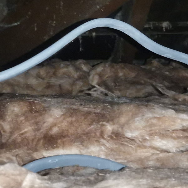
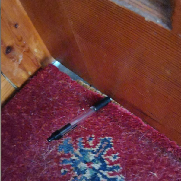
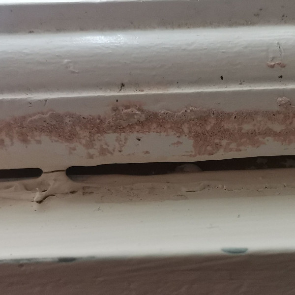
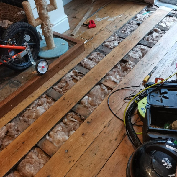
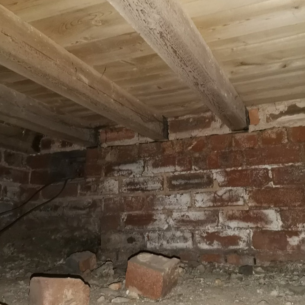
Under floor insulation can be tricky to monitor or inspect, as usually it will be installed via a somewhat restricted crawl space. If installed correctly, any hatches would have been draught proofed and insulated, so disturbing this would be detrimental. The Installers should have made photographic evidence available to the retrofit coordinator to back up the installation procedure. Below are what a can be visually monitored on UFI.